Software Architecture
Introduction
Document Purpose
The purpose of this document is to document the architecture of the tic4eebus application.
Application Scope
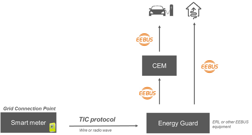
The tic4eebus application allows limiting an electric vehicle (EV) charging station based on the available energy provided by a Linky meter.
The software implements the OPEV use case of the EEBUS standard by acting as an energy management system (Energy Guard) to control the EV charging station (CEM) based on data read from the Linky meter (Smart Meter).
Architecture Overview
General Description
Use Case
The tic4eebus application interacts with five actors:
The Clock
The File System
The Database
The TIC2WebSocket API
The EEBUS Stack
The Clock
Triggering the available energy adjustment
The File System
Storing application business data
The Database
Accessing application business data (visualization, processing, etc.)
The TIC2WebSocket API
Receiving Linky meter data
The EEBUS Stack
Limiting electric vehicle charging
General description General description tic4eebus Receive Linky meter data Limit electric vehicle charging Adjust available energy Save business data Clock File System Database TIC2WebSocket API EEBUS Stack include include include General description General description tic4eebus Receive Linky meter data Limit electric vehicle charging Adjust available energy Save business data Clock File System Database TIC2WebSocket API EEBUS Stack include include include Main Components
The tic4eebus application contains:
The main
The config
The ems
The ems.data
The linkymeter
The evse
It uses two main external dependencies:
The TIC2WebSocket
The eebus-go
Main components Main components tic4eebus ems main config linkymeter evse CSV InfluxDb data TIC2WebSocket eebus-go use use use save save use use use use use Main components Main components tic4eebus ems main config linkymeter evse CSV InfluxDb data TIC2WebSocket eebus-go use use use save save use use use use use Detailed Architecture View
main component
Description
The main
At startup, it manages:
Command line interpretation (function main.parseCommandLine
Configuration loading (function config.LoadConfig
Logger initialization (function main.initLogger
Energy management system startup (method Start ems.EnergyGuard
At shutdown, it manages:
Energy management system shutdown (method Stop ems.EnergyGuard
Dependencies
Internal Dependencies
The main
The config
The ems
External Dependencies
The main module uses 2 external dependencies:
The file-rotatelogs
The logrus
Class Diagram
The following class diagram describes the main
main component classes main component classes main config ems Inputs configFilePath string showVersion bool main init() parseCommandLine() (inputs Inputs) initLogger(logConfig config.LogConfig) start() stop() LogConfig Config Log LogConfig config LoadConfig(configFilePath string) (Config, error) energyguard NewEnergyGuard(config Config) *EnergyGuard EnergyGuard Start() Stop() main component classes main component classes main config ems Inputs configFilePath string showVersion bool main init() parseCommandLine() (inputs Inputs) initLogger(logConfig config.LogConfig) start() stop() LogConfig Config Log LogConfig config LoadConfig(configFilePath string) (Config, error) energyguard NewEnergyGuard(config Config) *EnergyGuard EnergyGuard Start() Stop() config component
Description
The config
It uses:
The configuration for the overload protection algorithm implementing the OPEV use case of the EEBUS standard (class config.OverloadProtectionConfig
The electric vehicle data access configuration (class config.VehicleConfig
The charging station data access configuration (class config.WallboxConfig
The application logging configuration (class config.LogConfig
The application data model persistence configuration (class config.DataModelConfig
The Linky meter TIC access configuration (class config.TeleInformationClientConfig
The EEBUS communication configuration (class config.EEBUSConfig
Dependencies
Internal Dependencies
The config
External Dependencies
The config
The logrus
The yaml
Class Diagram
The following class diagram describes the config
config component classes config component classes config CurrentLimitConfig ValueInAmps float64 LockDelayInSeconds float64 FileRotationConfig PeriodInHours int PeriodCount int PeriodPattern string CsvConfig FilePath string Rotation FileRotationConfig InfluxDbConfig Bucket string Org string Token string IpAddress string TcpPort int Tic2WebsocketConfig IpAddress string TcpPort int TicIdentifierConfig SerialNumber string OverloadProtectionConfig Enable bool RunningPeriodInSeconds int CurrentLimit CurrentLimitConfig VehicleConfig UpdateDataPeriodInSeconds int DataPersistent bool WallboxConfig UpdateDataPeriodInSeconds int DataPersistent bool LogConfig Level log.Level FilePath string Rotation FileRotationConfig DataModelConfig Csv *CsvConfig InfluxDb *InfluxDbConfig TeleInformationClientConfig Tic2Websocket Tic2WebsocketConfig TicIdentifier TicIdentifierConfig EebusConfig ServerPort int RemoteSki string CertificateFilePath string PrivateKeyFilePath string VendorCode string DeviceBrand string DeviceModel string SerialNumber string HeartbeatTimeoutInSeconds int Config OverloadProtection OverloadProtectionConfig Vehicle VehicleConfig Wallbox WallboxConfig Log LogConfig DataModel DataModelConfig TeleInformationClient TeleInformationClientConfig Eebus EebusConfig config LoadConfig(configFilePath string) (Config, error) config component classes config component classes config CurrentLimitConfig ValueInAmps float64 LockDelayInSeconds float64 FileRotationConfig PeriodInHours int PeriodCount int PeriodPattern string CsvConfig FilePath string Rotation FileRotationConfig InfluxDbConfig Bucket string Org string Token string IpAddress string TcpPort int Tic2WebsocketConfig IpAddress string TcpPort int TicIdentifierConfig SerialNumber string OverloadProtectionConfig Enable bool RunningPeriodInSeconds int CurrentLimit CurrentLimitConfig VehicleConfig UpdateDataPeriodInSeconds int DataPersistent bool WallboxConfig UpdateDataPeriodInSeconds int DataPersistent bool LogConfig Level log.Level FilePath string Rotation FileRotationConfig DataModelConfig Csv *CsvConfig InfluxDb *InfluxDbConfig TeleInformationClientConfig Tic2Websocket Tic2WebsocketConfig TicIdentifier TicIdentifierConfig EebusConfig ServerPort int RemoteSki string CertificateFilePath string PrivateKeyFilePath string VendorCode string DeviceBrand string DeviceModel string SerialNumber string HeartbeatTimeoutInSeconds int Config OverloadProtection OverloadProtectionConfig Vehicle VehicleConfig Wallbox WallboxConfig Log LogConfig DataModel DataModelConfig TeleInformationClient TeleInformationClientConfig Eebus EebusConfig config LoadConfig(configFilePath string) (Config, error) linkymeter component
Description
The linkymeter component is responsible for accessing Linky meter data.
It manages:
Access to the interface (websocket server) provided by the TIC2WebSocket application (class linkymeter.TIC2WebSocketClient
Retrieving meter data from messages sent by TIC2WebSocket (function linkymeter.ComputeMeterData
Dependencies
Internal Dependencies
The linkymeter
External Dependencies
The linkymeter module uses 4 external dependencies:
The uuid
The websocket
The mapstructure
The logrus
Class Diagram
The following class diagram describes the linkymeter
linkymeter component classes linkymeter component classes linkymeter OnTicData OnTicData(ticData TicData) OnTicError OnTicError(ticError TicError) OnTicAbnormalClosure OnTicAbnormalClosure() TicData Mode string CaptureDateTime string Identifier TicIdentifier Content map[string]string TicError ErrorCode int ErrorMessage string Identifier TicIdentifier TicIdentifier SerialNumber string PortName string PortId string Tic2WebsocketClient Connect(host string) error GetAvailableTics() ([]TicIdentifier,error) SubscribeTic ( onData OnTicData, onError OnTicError, onAbnormalClosure OnTicAbnormalClosure, identifier TicIdentifier ) (string, error) UnsubscribeTic(subscriptionId string) error Close() error tic NewTic2WebsocketClient() *Tic2WebsocketClient MeterData SerialNumber string DateTime string BreakerOpened bool PhaseCount int OverloadPowerLimit int OverloadPowerLimitPerPhase []float64 RmsVoltagePerPhase []int RmsCurrentPerPhase []float64 ApparentImportPower int ApparentImportPowerPerPhase []int AvailableCurrentPerPhase []float64 data ComputeMeterData(ticContent map[string]string) MeterData linkymeter component classes linkymeter component classes linkymeter OnTicData OnTicData(ticData TicData) OnTicError OnTicError(ticError TicError) OnTicAbnormalClosure OnTicAbnormalClosure() TicData Mode string CaptureDateTime string Identifier TicIdentifier Content map[string]string TicError ErrorCode int ErrorMessage string Identifier TicIdentifier TicIdentifier SerialNumber string PortName string PortId string Tic2WebsocketClient Connect(host string) error GetAvailableTics() ([]TicIdentifier,error) SubscribeTic ( onData OnTicData, onError OnTicError, onAbnormalClosure OnTicAbnormalClosure, identifier TicIdentifier ) (string, error) UnsubscribeTic(subscriptionId string) error Close() error tic NewTic2WebsocketClient() *Tic2WebsocketClient MeterData SerialNumber string DateTime string BreakerOpened bool PhaseCount int OverloadPowerLimit int OverloadPowerLimitPerPhase []float64 RmsVoltagePerPhase []int RmsCurrentPerPhase []float64 ApparentImportPower int ApparentImportPowerPerPhase []int AvailableCurrentPerPhase []float64 data ComputeMeterData(ticContent map[string]string) MeterData evse component
Description
The evse
It uses:
The charging station configuration (class config.WallboxConfig
The electric vehicle configuration (class config.VehicleConfig
The charging station component handling EEBUS messages related to the station (class evse.Wallbox
The electric vehicle component handling EEBUS messages related to the vehicle (class evse.Vehicle
Dependencies
Internal Dependencies
The evse
External Dependencies
The evse module uses 5 external dependencies:
The eebus-go
The spine-go
The gocron
The uuid
The logrus
Class Diagram
The following class diagram describes the synchronizer component and its internal dependencies:
evse component classes evse component classes config evse WallboxConfig UpdateDataPeriodInSeconds int DataPersistent bool VehicleConfig UpdateDataPeriodInSeconds int DataPersistent bool onWallboxData onWallboxData(wallboxData map[string]interface{}) onWallboxConnected onWallboxConnected() onWallboxDisconnected onWallboxDisconnected() onWallboxSupported onWallboxSupported() onVehicleData onVehicleData(vehicleData map[string]interface{}) onVehicleConnected onVehicleConnected() onVehicleDisconnected onVehicleDisconnected() onVehicleOpevSupported onVehicleOpevSupported() Wallbox EnableRemoteConnection() DisableRemoteConnection() SubscribeData ( onData onWallboxData, onConnected onWallboxConnected, onDisconnected onWallboxDisconnected, onSupported onWallboxSupported ) (id string) UnsubscribeData(id string) error Vehicle EnableRemoteConnection() DisableRemoteConnection() SubscribeData ( onData onVehicleData, onConnected onVehicleConnected, onDisconnected onVehicleDisconnected, onOPEVSupported onVehicleOpevSupported ) (id string) UnsubscribeData(id string) error wallbox NewWallbox ( service api.ServiceInterface, localEntity spineapi.EntityLocalInterface, config config.WallboxConfig ) *Wallbox vehicle NewVehicle ( service api.ServiceInterface, localEntity spineapi.EntityLocalInterface, config config.VehicleConfig ) *Vehicle evse component classes evse component classes config evse WallboxConfig UpdateDataPeriodInSeconds int DataPersistent bool VehicleConfig UpdateDataPeriodInSeconds int DataPersistent bool onWallboxData onWallboxData(wallboxData map[string]interface{}) onWallboxConnected onWallboxConnected() onWallboxDisconnected onWallboxDisconnected() onWallboxSupported onWallboxSupported() onVehicleData onVehicleData(vehicleData map[string]interface{}) onVehicleConnected onVehicleConnected() onVehicleDisconnected onVehicleDisconnected() onVehicleOpevSupported onVehicleOpevSupported() Wallbox EnableRemoteConnection() DisableRemoteConnection() SubscribeData ( onData onWallboxData, onConnected onWallboxConnected, onDisconnected onWallboxDisconnected, onSupported onWallboxSupported ) (id string) UnsubscribeData(id string) error Vehicle EnableRemoteConnection() DisableRemoteConnection() SubscribeData ( onData onVehicleData, onConnected onVehicleConnected, onDisconnected onVehicleDisconnected, onOPEVSupported onVehicleOpevSupported ) (id string) UnsubscribeData(id string) error wallbox NewWallbox ( service api.ServiceInterface, localEntity spineapi.EntityLocalInterface, config config.WallboxConfig ) *Wallbox vehicle NewVehicle ( service api.ServiceInterface, localEntity spineapi.EntityLocalInterface, config config.VehicleConfig ) *Vehicle ems component
Description
The ems
It uses:
The global application configuration (class config.Config
The TIC2WebSocket client to receive Linky meter data (class linkymeter.Tic2WebSocketClient
The conversion of raw Linky meter data to business data (function linkymeter.ComputeMeterData
Application data persistence (class ems.data.DataSynchronizer
Electric vehicle data retrieval (class evse.Vehicle
Charging station data retrieval (class evse.Wallbox
Dependencies
Internal Dependencies
The ems
The config
The linkymeter
The evse
The ems.data
External Dependencies
The ems component uses 7 external dependencies:
The eebus-go
The ship-go
The spine-go
The gocron
The cmp
The uuid
The logrus
Class Diagram
The following class diagram describes the ems component and its internal dependencies:
Classes of ems component Classes of ems component ems data config evse linkymeter onData onData(data data.DataModel) EnergyGuard Start() Stop() Energy manager startup SubscribeData(onData onData) (id string) UnsubscribeData(id string) error Energy manager data subscription Trace(args ...interface{}) Tracef(format string, args ...interface{}) Debug(args ...interface{}) Debugf(format string, args ...interface{}) Info(args ...interface{}) Infof(format string, args ...interface{}) Error(args ...interface{}) Errorf(format string, args ...interface{}) Logging interface RemoteSKIConnected(service api.ServiceInterface, ski string) RemoteSKIDisconnected(service api.ServiceInterface, ski string) VisibleRemoteServicesUpdated(service api.ServiceInterface, entries []shipapi.RemoteService) ServiceShipIDUpdate(ski string, shipdID string) ServicePairingDetailUpdate(ski string, detail *shipapi.ConnectionStateDetail) AllowWaitingForTrust(ski string) bool EEBUS service interface energyguard NewEnergyGuard(config.Config) (*EnergyGuard) DataSynchronizer DataModel OverloadProtectionData DiagnosisData DataModelConfig Config Vehicle Wallbox MeterData Tic2WebSocketClient Classes of ems component Classes of ems component ems data config evse linkymeter onData onData(data data.DataModel) EnergyGuard Start() Stop() Energy manager startup SubscribeData(onData onData) (id string) UnsubscribeData(id string) error Energy manager data subscription Trace(args ...interface{}) Tracef(format string, args ...interface{}) Debug(args ...interface{}) Debugf(format string, args ...interface{}) Info(args ...interface{}) Infof(format string, args ...interface{}) Error(args ...interface{}) Errorf(format string, args ...interface{}) Logging interface RemoteSKIConnected(service api.ServiceInterface, ski string) RemoteSKIDisconnected(service api.ServiceInterface, ski string) VisibleRemoteServicesUpdated(service api.ServiceInterface, entries []shipapi.RemoteService) ServiceShipIDUpdate(ski string, shipdID string) ServicePairingDetailUpdate(ski string, detail *shipapi.ConnectionStateDetail) AllowWaitingForTrust(ski string) bool EEBUS service interface energyguard NewEnergyGuard(config.Config) (*EnergyGuard) DataSynchronizer DataModel OverloadProtectionData DiagnosisData DataModelConfig Config Vehicle Wallbox MeterData Tic2WebSocketClient ems.data component
Description
The ems.data data model .
It uses:
The application data model configuration (class config.DataModelConfig
The application data model (class ems.data.DataModel
The data model management interface (class ems.data.DataSynchronizer
The data model CSV file persistence interface (class ems.data.CsvWriter
The data model InfluxDb database persistence interface (class ems.data.InfluxDbWriter
Dependencies
Internal Dependencies
The ems
The config
The linkymeter
The evse
External Dependencies
The ems component uses 6 external dependencies:
The eebus-go
The spine-go
The influxdb-client-go
The cmp
The file-rotatelogs
The logrus
Class Diagram
The following class diagram describes the ems.data component and its internal dependencies:
ems.data component classes ems.data component classes ems data linkymeter config evse DataWriter Save(model DataModel) CsvWriter Save(model DataModel) InfluxDbWriter Save(model DataModel) synchronizer NewDataSynchronizer(dataModelConfig config.DataModelConfig) *DataSynchronizer DataSynchronizer IsConnected() (isConnected bool) SetIsConnected(isConnected bool) (hasChanged bool) HasMeterData() (hasMeterData bool) SetHasMeterData(hasMeterData bool) (hasChanged bool) IsOpevSupported() (isOpevSupported bool) SetIsOpevSupported(isOpevSupported bool) (hasChanged bool) Connections GetVehicle() (vehicle map[string]interface{}) SetVehicle(vehicle map[string]interface{}) (hasChanged bool) GetWallbox() (wallbox map[string]interface{}) SetWallbox(wallbox map[string]interface{}) (hasChanged bool) GetMeter() (meter linkymeter.MeterData) SetMeter(meter linkymeter.MeterData) (hasChanged bool) Data GetMeterMinAvailableCurrent() (minAvailableCurrent float64) DisableOverloadProtectionActive() GetOverloadProtectionValue() (limitValue float64) SetOverloadProtectionValue(limitValue float64) SetOverloadProtectionResult(result model.ResultDataType) (hasChanged bool) SetOverloadProtectionLockStart(lockStart time.Time) (hasChanged bool) GetOverloadProtectionLockDuration() (lockDuration time.Duration) SetOverloadProtectionLockActive(lockActive bool) (hasChanged bool) Overload protection GetDiagnosisState() *model.DeviceDiagnosisStateDataType SetDiagnosis(operatingState model.DeviceDiagnosisOperatingStateType, lastErrorCode model.LastErrorCodeType) (hasChanged bool) Diagnostics GetModel() (model DataModel) Print() Model OverloadProtectionData Active bool Value float64 Start time.Time ResultCode model.ErrorNumberType ResultDescription model.DescriptionType LockActive bool LockStart time.Time DiagnosisData OperatingState model.DeviceDiagnosisOperatingStateType LastErrorCode model.LastErrorCodeType DataModel IsConnected bool HasMeterData bool IsOpevSupported bool Vehicle map[string]interface{} Wallbox map[string]interface{} Meter linkymeter.MeterData OverloadProtection OverloadProtectionData Diagnosis DiagnosisData MeterData DataModelConfig vehicle wallbox ems.data component classes ems.data component classes ems data linkymeter config evse DataWriter Save(model DataModel) CsvWriter Save(model DataModel) InfluxDbWriter Save(model DataModel) synchronizer NewDataSynchronizer(dataModelConfig config.DataModelConfig) *DataSynchronizer DataSynchronizer IsConnected() (isConnected bool) SetIsConnected(isConnected bool) (hasChanged bool) HasMeterData() (hasMeterData bool) SetHasMeterData(hasMeterData bool) (hasChanged bool) IsOpevSupported() (isOpevSupported bool) SetIsOpevSupported(isOpevSupported bool) (hasChanged bool) Connections GetVehicle() (vehicle map[string]interface{}) SetVehicle(vehicle map[string]interface{}) (hasChanged bool) GetWallbox() (wallbox map[string]interface{}) SetWallbox(wallbox map[string]interface{}) (hasChanged bool) GetMeter() (meter linkymeter.MeterData) SetMeter(meter linkymeter.MeterData) (hasChanged bool) Data GetMeterMinAvailableCurrent() (minAvailableCurrent float64) DisableOverloadProtectionActive() GetOverloadProtectionValue() (limitValue float64) SetOverloadProtectionValue(limitValue float64) SetOverloadProtectionResult(result model.ResultDataType) (hasChanged bool) SetOverloadProtectionLockStart(lockStart time.Time) (hasChanged bool) GetOverloadProtectionLockDuration() (lockDuration time.Duration) SetOverloadProtectionLockActive(lockActive bool) (hasChanged bool) Overload protection GetDiagnosisState() *model.DeviceDiagnosisStateDataType SetDiagnosis(operatingState model.DeviceDiagnosisOperatingStateType, lastErrorCode model.LastErrorCodeType) (hasChanged bool) Diagnostics GetModel() (model DataModel) Print() Model OverloadProtectionData Active bool Value float64 Start time.Time ResultCode model.ErrorNumberType ResultDescription model.DescriptionType LockActive bool LockStart time.Time DiagnosisData OperatingState model.DeviceDiagnosisOperatingStateType LastErrorCode model.LastErrorCodeType DataModel IsConnected bool HasMeterData bool IsOpevSupported bool Vehicle map[string]interface{} Wallbox map[string]interface{} Meter linkymeter.MeterData OverloadProtection OverloadProtectionData Diagnosis DiagnosisData MeterData DataModelConfig vehicle wallbox Interaction Models
Sequence Diagrams
The sequence diagrams illustrate interactions between components concerning:
Application startup
Application shutdown
Energy management system startup
Energy management system shutdown
Energy management system periodic regulation
Application Startup
Application startup is described by the following sequence diagram:
Application startup Application startup main main main main main config EnergyGuard System main config Inputs EnergyGuard System System main main config config Inputs EnergyGuard main main main main main config EnergyGuard main() init() Command line parseCommandLine() new Inputs update input data with command line input data Configuration LoadConfig() configuration Logging initLogger() logger initialized Energy management system new EnergyGuard creation with configuration parameters application initialize start() Start() energy management system started application started Application startup Application startup main main main main main config EnergyGuard System main config Inputs EnergyGuard System System main main config config Inputs EnergyGuard main main main main main config EnergyGuard main() init() Command line parseCommandLine() new Inputs update input data with command line input data Configuration LoadConfig() configuration Logging initLogger() logger initialized Energy management system new EnergyGuard creation with configuration parameters application initialize start() Start() energy management system started application started Application Shutdown
Application shutdown is described by the following sequence diagram :
Application shutdown Application shutdown main main EnergyGuard System main EnergyGuard System System main main EnergyGuard EnergyGuard main main EnergyGuard SIGSTOP [CTRL + C] stop() Energy management system Stop() energy management stopped application stopped exit() Application shutdown Application shutdown main main EnergyGuard System main EnergyGuard System System main main EnergyGuard EnergyGuard main main EnergyGuard SIGSTOP [CTRL + C] stop() Energy management system Stop() energy management stopped application stopped exit() Energy Management System Startup
Energy management system startup is described by the following sequence diagram :
Energy management system startup Energy management system startup EnergyGuard Tic2WebSocketClient Tic2WebSocketClient Tic2WebSocketClient EEBUS Service EEBUS Service Scheduler Scheduler Scheduler TICIdentifier TICIdentifier main EnergyGuard Tic2WebSocketClient EEBUS Service Scheduler TICIdentifier main main EnergyGuard EnergyGuard Tic2WebSocketClient Tic2WebSocketClient EEBUS Service EEBUS Service Scheduler Scheduler TICIdentifier EnergyGuard Tic2WebSocketClient Tic2WebSocketClient Tic2WebSocketClient EEBUS Service EEBUS Service Scheduler Scheduler Scheduler TICIdentifier TICIdentifier Start() Start receiving data from Linky meter Connect(ticServiceHost) connected with Tic2WebSocket GetAvailableTics() available TIC streams alt [Meter serial number exists in config] loop [available TIC streams] alt [TIC stream meter serial number matches config] new TICIdentifier update serial number Serial number updated [Meter serial number empty in config] loop [available TIC streams] alt [TIC stream meter serial number exists] new TICIdentifier update serial number Serial number updated SubscribeTIC(onData,onError,ticIdentifier) meter data subscription successful Start EEBUS communication RegisterRemoteSKI(config.EEBUS.RemoteSKI) Charging station SKI identifier registered Start() EEBUS service started Start overload protection Every(config.OverloadProtection.RunningPeriodInSeconds) Overload protection execution period defined Seconds() Overload protection execution period converted to seconds Do(runOverloadProtection) Overload protection function configured energy management system started Energy management system startup Energy management system startup EnergyGuard Tic2WebSocketClient Tic2WebSocketClient Tic2WebSocketClient EEBUS Service EEBUS Service Scheduler Scheduler Scheduler TICIdentifier TICIdentifier main EnergyGuard Tic2WebSocketClient EEBUS Service Scheduler TICIdentifier main main EnergyGuard EnergyGuard Tic2WebSocketClient Tic2WebSocketClient EEBUS Service EEBUS Service Scheduler Scheduler TICIdentifier EnergyGuard Tic2WebSocketClient Tic2WebSocketClient Tic2WebSocketClient EEBUS Service EEBUS Service Scheduler Scheduler Scheduler TICIdentifier TICIdentifier Start() Start receiving data from Linky meter Connect(ticServiceHost) connected with Tic2WebSocket GetAvailableTics() available TIC streams alt [Meter serial number exists in config] loop [available TIC streams] alt [TIC stream meter serial number matches config] new TICIdentifier update serial number Serial number updated [Meter serial number empty in config] loop [available TIC streams] alt [TIC stream meter serial number exists] new TICIdentifier update serial number Serial number updated SubscribeTIC(onData,onError,ticIdentifier) meter data subscription successful Start EEBUS communication RegisterRemoteSKI(config.EEBUS.RemoteSKI) Charging station SKI identifier registered Start() EEBUS service started Start overload protection Every(config.OverloadProtection.RunningPeriodInSeconds) Overload protection execution period defined Seconds() Overload protection execution period converted to seconds Do(runOverloadProtection) Overload protection function configured energy management system started Energy Management System Shutdown
Energy manager shutdown is described by the following sequence diagram :
Energy management system shutdown Energy management system shutdown EnergyGuard Tic2WebSocketClient Tic2WebSocketClient EEBUS Service Vehicle Wallbox Scheduler main EnergyGuard Tic2WebSocketClient EEBUS Service Vehicle Wallbox Scheduler main main EnergyGuard EnergyGuard Tic2WebSocketClient Tic2WebSocketClient EEBUS Service EEBUS Service Vehicle Vehicle Wallbox Wallbox Scheduler Scheduler EnergyGuard Tic2WebSocketClient Tic2WebSocketClient EEBUS Service Vehicle Wallbox Scheduler Stop() Stop overload protection Stop() Overload protection execution scheduler stopped Stop EEBUS communication Shutdown() EEBUS service stopped DisableRemoteConnection() Vehicle data update disabled DisableRemoteConnection() Charging station data update disabled Stop receiving data from Linky meter Unsubscribe(ticServiceSubcriptionId) Meter data subscription ended Close() Connection with Tic2WebSocket closed Energy management system stopped Energy management system shutdown Energy management system shutdown EnergyGuard Tic2WebSocketClient Tic2WebSocketClient EEBUS Service Vehicle Wallbox Scheduler main EnergyGuard Tic2WebSocketClient EEBUS Service Vehicle Wallbox Scheduler main main EnergyGuard EnergyGuard Tic2WebSocketClient Tic2WebSocketClient EEBUS Service EEBUS Service Vehicle Vehicle Wallbox Wallbox Scheduler Scheduler EnergyGuard Tic2WebSocketClient Tic2WebSocketClient EEBUS Service Vehicle Wallbox Scheduler Stop() Stop overload protection Stop() Overload protection execution scheduler stopped Stop EEBUS communication Shutdown() EEBUS service stopped DisableRemoteConnection() Vehicle data update disabled DisableRemoteConnection() Charging station data update disabled Stop receiving data from Linky meter Unsubscribe(ticServiceSubcriptionId) Meter data subscription ended Close() Connection with Tic2WebSocket closed Energy management system stopped Energy Managerment System Periodic Regulation
Energy management system periodic regulation is explained by the flowchart below :
Energy management system periodic regulation flowchart Energy management system periodic regulation flowchart Calculate charge limitation lock duration Lock duration elapsed? yes no Calculate minimum available current across all phases Overload protection necessary? yes no Decrease vehicle maximum charging current value Increase vehicle maximum charging current value Update lock parameters Maintain vehicle maximum charging current value Apply vehicle maximum charging current value yes Meter data available? Energy management system periodic regulation flowchart Energy management system periodic regulation flowchart Calculate charge limitation lock duration Lock duration elapsed? yes no Calculate minimum available current across all phases Overload protection necessary? yes no Decrease vehicle maximum charging current value Increase vehicle maximum charging current value Update lock parameters Maintain vehicle maximum charging current value Apply vehicle maximum charging current value yes Meter data available? Energy management system periodic regulation is described in detail by the following sequence diagram :
Energy management system periodic regulation Energy management system periodic regulation EnergyGuard EnergyGuard EnergyGuard EnergyGuard EnergyGuard DataSynchronizer DataSynchronizer DataSynchronizer DataSynchronizer DataSynchronizer DataSynchronizer DataSynchronizer DataSynchronizer Vehicle Vehicle Vehicle Scheduler EnergyGuard DataSynchronizer Vehicle Scheduler Scheduler EnergyGuard EnergyGuard DataSynchronizer DataSynchronizer Vehicle Vehicle EnergyGuard EnergyGuard EnergyGuard EnergyGuard EnergyGuard DataSynchronizer DataSynchronizer DataSynchronizer DataSynchronizer DataSynchronizer DataSynchronizer DataSynchronizer DataSynchronizer Vehicle Vehicle Vehicle runOverloadProtection() IsConnected() EEBUS connection state IsConnected() EV connection state GetVehicleCurrentLimits() EV current limitations (min, max) HasMeterData() Connection state with Linky meter alt [Linky meter data NOT available] currentLimit = minCurrentLimit Update vehicle charge limitation to apply [Linky meter data available] GetOverloadProtectionValue() Vehicle maximum charging current GetOverloadProtectionLockDuration() Charge limitation lock duration alt [Lock duration elapsed] SetOverloadProtectionActive(false) Update vehicle charge limitation activation state GetMeterMinAvailableCurrent() Minimum available current across all phases alt [Overload protection necessary] currentLimit = loadControlLimit - abs(minAvailableCurrent) Decrease vehicle maximum charging current value [Overload protection NOT necessary] currentLimit = loadControlLimit + abs(minAvailableCurrent) Increase vehicle maximum charging current value SetOverloadProtectionLockStart(now) Update charge limitation lock start timestamp [Lock duration NOT elapsed] currentLimit = loadControlLimit Maintain vehicle maximum charging current value WriteLoadControlLimits(currentLimit) Vehicle maximum charging current applied SetOverloadProtectionValue(currentLimit) Update vehicle maximum charging current value Overload protection executed Energy management system periodic regulation Energy management system periodic regulation EnergyGuard EnergyGuard EnergyGuard EnergyGuard EnergyGuard DataSynchronizer DataSynchronizer DataSynchronizer DataSynchronizer DataSynchronizer DataSynchronizer DataSynchronizer DataSynchronizer Vehicle Vehicle Vehicle Scheduler EnergyGuard DataSynchronizer Vehicle Scheduler Scheduler EnergyGuard EnergyGuard DataSynchronizer DataSynchronizer Vehicle Vehicle EnergyGuard EnergyGuard EnergyGuard EnergyGuard EnergyGuard DataSynchronizer DataSynchronizer DataSynchronizer DataSynchronizer DataSynchronizer DataSynchronizer DataSynchronizer DataSynchronizer Vehicle Vehicle Vehicle runOverloadProtection() IsConnected() EEBUS connection state IsConnected() EV connection state GetVehicleCurrentLimits() EV current limitations (min, max) HasMeterData() Connection state with Linky meter alt [Linky meter data NOT available] currentLimit = minCurrentLimit Update vehicle charge limitation to apply [Linky meter data available] GetOverloadProtectionValue() Vehicle maximum charging current GetOverloadProtectionLockDuration() Charge limitation lock duration alt [Lock duration elapsed] SetOverloadProtectionActive(false) Update vehicle charge limitation activation state GetMeterMinAvailableCurrent() Minimum available current across all phases alt [Overload protection necessary] currentLimit = loadControlLimit - abs(minAvailableCurrent) Decrease vehicle maximum charging current value [Overload protection NOT necessary] currentLimit = loadControlLimit + abs(minAvailableCurrent) Increase vehicle maximum charging current value SetOverloadProtectionLockStart(now) Update charge limitation lock start timestamp [Lock duration NOT elapsed] currentLimit = loadControlLimit Maintain vehicle maximum charging current value WriteLoadControlLimits(currentLimit) Vehicle maximum charging current applied SetOverloadProtectionValue(currentLimit) Update vehicle maximum charging current value Overload protection executed Technical Infrastructure
Programming Languages
The tic4eebus project is entirely developed in Go.
It is compatible with Go versions 1.23 and later.
Database
The database used to access the application's data model is an InfluxDb database.
Its structure consists of only one bucket (named demo-bucket) and one measurement (named EnergyGuard) belonging to the same organization "demo-org".
The data available in the table are :
InfluxDB database structure InfluxDB database structure Org: demo-org Bucket: demo-bucket «measurement» EnergyGuard time : timestamp EnergyGuard : string «tag» IsConnected : bool «field» HasMeterData : bool «field» IsOpevSupported : bool «field» Diagnosis_LastErrorCode : string «field» OverloadProtection_Value : float «field» Energy manager Meter_DateTime : string «field» Meter_BreakerOpened : bool «field» Meter_OverLoadCurrentLimit1 : float «field» Meter_OverLoadCurrentLimit2 : float «field» Meter_OverLoadCurrentLimit3 : float «field» Meter_RmsCurrent1 : float «field» Meter_RmsCurrent2 : float «field» Meter_RmsCurrent3 : float «field» Linky meter EV_CurrentPerPhase1 : float «field» EV_CurrentPerPhase2 : float «field» EV_CurrentPerPhase3 : float «field» Electric vehicle InfluxDB database structure InfluxDB database structure Org: demo-org Bucket: demo-bucket «measurement» EnergyGuard time : timestamp EnergyGuard : string «tag» IsConnected : bool «field» HasMeterData : bool «field» IsOpevSupported : bool «field» Diagnosis_LastErrorCode : string «field» OverloadProtection_Value : float «field» Energy manager Meter_DateTime : string «field» Meter_BreakerOpened : bool «field» Meter_OverLoadCurrentLimit1 : float «field» Meter_OverLoadCurrentLimit2 : float «field» Meter_OverLoadCurrentLimit3 : float «field» Meter_RmsCurrent1 : float «field» Meter_RmsCurrent2 : float «field» Meter_RmsCurrent3 : float «field» Linky meter EV_CurrentPerPhase1 : float «field» EV_CurrentPerPhase2 : float «field» EV_CurrentPerPhase3 : float «field» Electric vehicle Servers and Hosting
The tic4eebus application can be installed on multiple platforms (Raspberry Pi, PLC, Windows PC, Mac)
Security
Security Measures
All communication with the charging station is secured (see EEBUS standard)
Access Management
The tic4eebus application accesses the charging station via its SKI which is in the configuration file loaded at application startup.
Error Handling and Monitoring
Error Handling
During periodic regulation there are 6 main possible errors:
Loss of connection with TIC2WebSocket which provides Linky meter data
Absence of TIC stream with the Linky meter in TIC2WebSocket
Absence of message from the Linky meter in TIC2WebSocket
Loss of EEBUS connection with the electric vehicle charging station
Non-implementation of the OPEV use case of the EEBUS standard by the charging station
Failure to apply the electric vehicle current limitation
All errors are logged in the application log.
Each of these errors modifies the energy management system diagnostic data.
When the energy manager operational state is in error (see failure in the table), the charging station limits the electric vehicle with the minimum charging current.
Loss of Connection with TIC2WebSocket
The Tic2WebSocketClient WebSocket client of the tic4eebus application connects to the WebSocket server of the TIC2WebSocket application to retrieve Linky meter business data.
If the connection with the server fails or is cut, then the tic4eebus application cannot receive Linky meter business data.
A periodic connection recovery attempt is made until the connection is established.
Absence of Meter TIC Stream in TIC2WebSocket
After the Tic2WebSocketClient WebSocket client of the tic4eebus application connects to the WebSocket server of the TIC2WebSocket application, a request is sent to retrieve the list of available TIC streams.
When no stream is available or when the specified meter is not present in the available TIC streams, retrieving Linky meter business data is not possible.
Periodic requests to list available TIC streams are executed until a meter or the specified meter is detected.
Absence of Message from Meter in TIC2WebSocket
After the Tic2WebSocketClient WebSocket client of the tic4eebus application subscribes to a meter with the WebSocket server of the TIC2WebSocket application, messages containing business data are retrieved periodically (with a period varying between 1 and 3 seconds).
When the Linky meter has not sent a message (TIC frame) for 10 seconds, the meter business data is obsolete and it is considered that there is no data from the meter.
When a message (TIC frame) is received again, the message absence stops and the energy manager periodic regulation resumes normally.
Loss of Connection with Charging Station
At tic4eebus application startup, the EEBUS service connects to the charging station.
When the connection with the charging station fails or is cut, then the tic4eebus application can no longer regulate the electric vehicle charge limitation.
A periodic connection recovery attempt with the charging station is made by the EEBUS service.
Non-implementation of OPEV EEBUS Use Case in Charging Station
At tic4eebus application startup, the EEBUS service connects to the charging station.
When the connection with the charging station is established, the EEBUS standard use cases implemented by the station can be retrieved (not on all stations).
When an electric vehicle connects, new notifications appear to provide information about the EEBUS use cases related to the electric vehicle.
The OPEV use case that interests us allows limiting electric vehicle charging.
If this use case is not implemented, then vehicle regulation is not possible.
Failure to Apply Electric Vehicle Charge Limitation
In the energy manager periodic regulation, the vehicle current limitation value is calculated then applied if it is different from the current limitation value.
During current limitation application, the request can be rejected and therefore the regulation non-operational.
Periodic regulation continues anyway hoping that the next current limitation application request is not rejected.
In the current state, there is no tool to monitor the application state and performance.
Scalability
Scalability Strategies
Several evolution axes are possible:
Provide application state
Take into account the current drawn by the vehicle in periodic regulation
Conclusion
The tic4tic4eebus eebus application is a multi-platform implementation that allows implementing the OPEV use case with a Linky meter and an EEBUS-compatible charging station.